The BlueBerry device and its companion BlueHub control interface together form a robust platform for wireless optogenetic stimulation in freely moving animals. By linking multichannel LED pulses to external triggers in real time, researchers can investigate a variety of neural processes in naturalistic conditions without the need for specialized hardware expertise.Below is a User Manual for the BlueBerry System, detailing how the BlueBerry device and its BlueHub controller work together to provide flexible, closed-loop optogenetic stimulation. The BlueBerry device generates LED pulses according to user-defined parameters, while the BlueHub manages communication, configuration, and closed-loop triggering based on external signals. By combining these components, researchers can conduct advanced neuroscience experiments—ranging from multi-animal social interactions to large-scale maze navigation—using a straightforward, open-source approach. The following sections explain each component’s hardware features, software controls, and the principles governing their interaction.

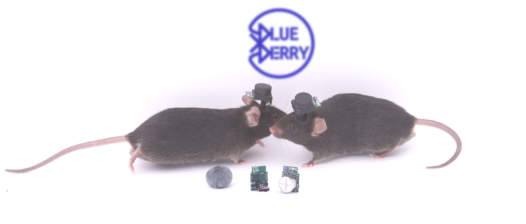
The BlueBerry is a lightweight (~1.5 g), battery-powered optogenetic device designed for experiments in freely moving animals. Its small size (approximately the dimensions of an actual blueberry) and off-the-shelf component construction make it accessible to labs with limited engineering resources. Featuring two independently controlled LED stimulation channels, BlueBerry excels in settings that require minimal interference with natural behavior, including multi-animal social paradigms, large-scale navigation tasks, and other scenarios where tethered fiber optics would be impractical. The sections below detail how BlueBerry processes stimulation commands, its physical layout, and the battery charging workflow.
BlueBerry is built around a Bluetooth Low Energy (BLE) module (RN4871) that receives command packets from the BlueHub. Each packet contains the necessary stimulation parameters—such as frequency, pulse width, number of pulses, and choice of LED channel(s). The RN4871 then communicates these parameters via an I²C bus to the ATtiny85 microcontroller, which interprets them in real time. Once it has decoded the instructions, the ATtiny85 drives the high-power LED outputs through a two-channel MOSFET stage, ensuring precise timing and current control for each stimulation pulse.
A low-dropout (LDO) regulator supplies 3.3 V from a small rechargeable lithium coin battery (e.g., VARTA CP1254-A3), maintaining stable operation of both the BLE module and the ATtiny85. A micro switch on the PCB toggles power to the entire device, while a surface-mounted status LED indicates the current operational state (e.g., searching for connection, connected, or actively stimulating). Finally, a micro-connector (Hirose BM23 series) provides an interface for charging and programming; the BlueBerry’s battery can be recharged through the dedicated charging stations on the BlueHub, and initial firmware configuration for both the BLE module and the ATtiny85 is also performed through this connector. By integrating these components into a compact PCB, BlueBerry delivers multichannel optogenetic stimulation in a lightweight form factor, making it well suited for extended experiments in freely moving animals.

BlueBerry includes a micro switch that controls its power. When the switch is slid to the “ON” position (as shown in the reference image), the device powers up. Initially, the indicator LED will exhibit a ramping pattern, indicating that the BlueBerry is active but not yet connected to a host device. If a controller like the BlueHub establishes a link, the indicator LED switches to a fast blink while the connection is negotiated, and then turns off once the link is stable. Whenever the BlueBerry receives a command packet—such as a new stimulation protocol—the indicator LED will pulse once at the start of the output LED sequence, confirming that it recognized and processed the incoming instructions.

BlueBerry provides two LED output channels, accessible through a 2×2 male connector on the board. When viewing the device from the bottom (see reference image), the left side of the connector corresponds to Output Channel 1, while the right side corresponds to Output Channel 2. To test your BlueBerry prior to animal experiments, attach a compatible LED implant to the connector—using tweezers, as shown in the reference image—so you can observe stimulation pulses directly. This setup allows you to verify that the device is functioning correctly before implantation or any additional experimental procedures.

The BlueHub unit includes dedicated charging ports for recharging the BlueBerry’s battery. This integrated design ensures a straightforward workflow to keep multiple BlueBerry devices powered for ongoing experiments.

The BlueHub is an Arduino-based control interface designed to manage multiple BlueBerry devices, facilitating effortless closed-loop optogenetic experiments without requiring extensive coding expertise. Equipped with four BNC input channels, the BlueHub can receive real-time signals from external behavioral frameworks—ranging from commercial systems like EthoVision to open-source platforms like DeepLabCut or EthoLoop. It is easy to assign stimulation protocols to each BNC input, allowing the BlueHub to trigger specific BlueBerry devices whenever relevant behavioral events are detected.
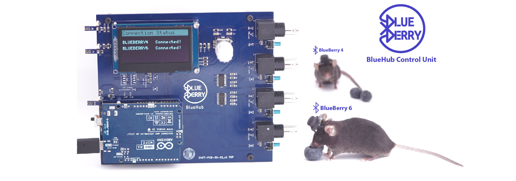
At the core of the BlueHub is an Arduino UNO Rev4, which manages Bluetooth Low Energy (BLE) communication with any number of BlueBerry devices. A rotary encoder and OLED screen provide an intuitive menu for configuring stimulation parameters—such as frequency, pulse width, and the number of pulses—and mapping them to each BNC input. This streamlined interface stores and retrieves settings from onboard EEPROM, letting users seamlessly switch between different experimental configurations. Additionally, two dedicated charging stations and one programming/charging station make it simple to recharge BlueBerry devices or upload new firmware as needed. By centralizing these functionalities, the BlueHub offers a straightforward, modular way to integrate wireless optogenetics into existing behavioral assays with minimal retooling.
When you power on the BlueHub (with its software correctly uploaded), an OLED screen displays the main menu, which offers three core functions:
You can navigate these options by rotating the rotary encoder clockwise or counterclockwise and select an option by pressing down on the encoder.

When you select “Scan for BlueBerry Devices,” the BlueHub enables its Bluetooth module and looks for active BlueBerry units within range. Only BlueBerry devices that have been previously configured (as described in the BlueBerry Software documentation) will be recognized. Once scanning is complete, the OLED will display a list of available BlueBerries. This step is primarily to confirm which devices are powered on and available. To return to the main menu at any time, press and hold the rotary encoder for two seconds.

Selecting “Create Configuration” leads you to the interface where you can define how each of the four BNC input channels should behave when triggered. Initially, you will see each BNC channel (labeled BNC1 through BNC4) along with five placeholder values in parentheses (x, x, x, x, x). These five values represent:
Once you enter a channel’s configuration, you can rotate the rotary encoder to move between these five fields and press the encoder to edit a particular field. After adjusting the values, returning to the channel overview confirms your settings. You can then edit the other BNC channels in the same way. Once all channels have been configured, you will have the option to save the settings to one of two configuration slots (Config 1 or Config 2). These slots are stored in the Arduino’s EEPROM, preserving your settings even if the device is turned off. After saving, navigate back to the main menu.

The “Load Configuration” menu lets you choose from the previously saved configurations (Config 1 or Config 2). Selecting a configuration displays an overview of how each BNC channel has been assigned: which BlueBerry, LED channel, frequency, pulse width, and number of pulses. To proceed, select “Start” to initiate the configuration. The BlueHub then attempts to connect to each BlueBerry device included in the loaded config and verifies their connectivity. Once all assigned BlueBerries are connected, the system is ready to respond to triggers on any of the four BNC inputs.

The four BNC inputs on the BlueHub detect 5V rising edges to initiate stimulation commands:
Blow is an example for two BNC channels assigned to two different BlueBerry devices with different stimulation protocols.

Each BNC port on the BlueHub has a button switch next to it for quick testing. Pressing this switch simulates a rising edge on the corresponding BNC input. If your BlueBerry device is properly configured, you should see immediate LED stimulation (or hear a motor response, etc.) as dictated by your assigned settings.

